
3D Printed Drones
and UAV structures.
A drone's success hinges on hundreds of interconnected engineering choices. From aerodynamic contours to software safety layers, each decision carries trade-offs in performance, reliability, cost, and regulatory compliance. This in-depth guide maps the design landscape for multirotor, fixed-wing, and hybrid UAVs.
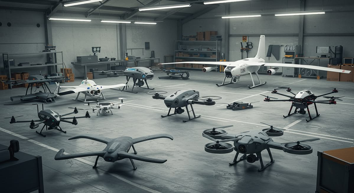
Lightweight rigidity defines endurance. ALT synthesizes material science, aerodynamics, propulsion, control, and regulatory design into airframes that are efficient, resilient, and accepted in increasingly crowded skies.
Structural integrity and materials.
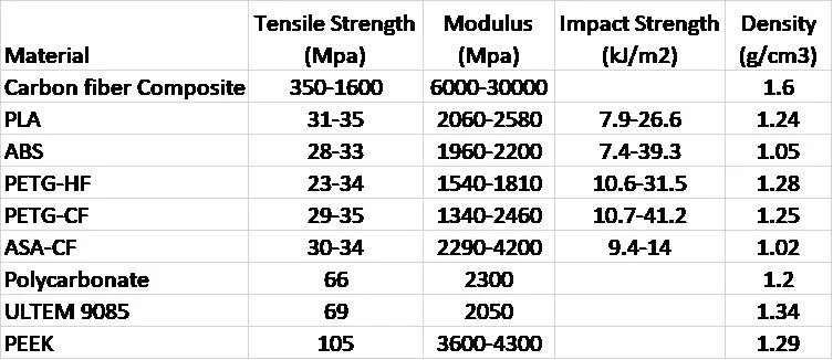
For avionic applications, materials generally need to be very strong (high tensile strength), stiff (high modulus), and lightweight (low density). For this reason, carbon fiber is the preferred material for structural regions. 3D printed materials with high toughness are desirable, especially when considering that a crash can easily crack conventional PLA or ABS frames. One of the advantages of 3D printing, however, is that parts can be fairly quickly reprinted, and hybrid printing to optimize materials for various functionalities is desirable. ASA and PETG give a good option for superior UV performance, which is important when exposed to the elements. The table below compares carbon fiber composite to most of the common filaments, and more exotic filaments that require high temperature deposition (PEEK and Ultem) and added cost — clearly carbon fiber composite has the best strength/weight ratio.
Comparison of strength and density for common drone materials.
Propulsion system engineering.
Brushless outrunners dominate small UAVs for their high torque and >85% peak efficiency. Optimal KV (RPM/V) lands where required thrust per motor matches propeller-specific power, preventing overstress. Electronic-Speed-Controllers (ESCs) demand low RDS(on) FETs and high PWM resolution to minimize switching loss and acoustic chatter.
Redundancy can arise at motor level (coaxial pairs) or vehicle level (hexacopters), trading excess mass for fault tolerance.
Motor selection
Thrust-per-motor matched to propeller power curve. High-torque outrunners with tuned KV avoid thermal and electrical overstress.
ESC switching
Low RDS(on) FETs and high PWM resolution cut switching losses and acoustic chatter on the drive stage.
Redundancy architectures
Coaxial motor pairs or hexacopter layouts trade mass for fault tolerance, at motor or vehicle level.
Aerodynamics and flight performance.
Efficient flight begins with clean airflow and the right propulsion geometry. Streamlining the fuselage, tilting arms, or adopting X/T-shaped frames reduces frontal area and drag. Computational fluid dynamics (CFD) or wind-tunnel validation around rotors confirms lift, thrust, and hover power predictions.
Diameter & pitch
Larger, lower-RPM propellers raise disk-loading efficiency yet enlarge the footprint.
Blade count & shape
Bi-blades typically yield lower drag but less thrust authority than tri-blades. Serrated or toroidal tips mute vortices, trimming 3–4 dB of tonal noise without lift loss.
Blade material
Carbon-fiber composites endure high RPM while minimizing flex-induced vibrations.
Multirotor configuration trades
NASA analyses show handling qualities and disturbance-rejection bandwidth improve when quadcopters scale to hexa- or octocopters, albeit with mass and cost penalties. Designers iterate rotor count against control authority, redundancy demands, and stowage envelope.
Energy density vs. weight
An extra 100 g battery may extend flight 4–6 min but pushes motors closer to their continuous current limit. Every energy decision is a structural and thermal decision too.
Power, batteries, and thermal pathways.
Key design checkpoints for the energy chain.
Energy density vs. weight
An extra 100 g of battery may extend flight 4–6 min but pushes motors closer to continuous current limit. Battery capacity is balanced against propulsion and structural budget.
BMS intelligence
Cell balancing, over-current protection, and SOH (state-of-health) algorithms avert mid-air failures before they happen.
Thermal pathways
Heat-sinking batteries through aluminum spines mitigates 60 °C pack hot-spots during aggressive discharges.
Control architecture and autonomy.
Modern flight controllers integrate IMUs, barometers, GNSS, and often vision or LiDAR SLAM sensors. Robust fault-tree analysis (FTA) combined with >19,500 h MTBF autopilot reliability targets reduce latent crash risk.
| Safety Layer | Implementation Highlights | Impact on Reliability |
|---|---|---|
| Hardware Redundancy | Dual CPU cores or triple modular autopilots with arbitration boards | Maintains control despite single-point CPU failure |
| Functional Redundancy | Diverse sensor fusion (e.g., GPS + optical flow) | Survives GNSS spoofing/dropouts |
| Handling-Quality Tuning | Controller bandwidth tuned >0.9 rad/s DRB for urban air mobility | Passenger-grade stability margins |
Safety systems and fail-safe logic.
Regulations increasingly demand that no single failure jeopardizes flight. Redundant power buses, "safe-core" flight code, and independent radio links backstop lost-link events. Popular fail-safe modes:
Return-to-Home (RTH)
Triggered by GNSS fix and altitude checks, bringing the aircraft back on lost link or low battery.
Land-Now
Autonomous descent initiated on battery reserve threshold, clearing the critical voltage envelope.
Parachute Deployment
Required for many >25 kg drones operating over crowd densities, arresting ballistic descent.
Noise mitigation and community acceptance.
Urban drone deliveries heighten acoustic scrutiny. Propeller tonal peaks (blade-pass frequency) dominate 70–90 dB hover noise. Solutions across the rotor and airframe:
Serrated Gurney flaps & toroidal loops
Re-distribute vortices, lowering peak SPL 2–4 dB without sacrificing thrust.
Bio-inspired tip curvature
Tip-vortex sound reduced without power loss, borrowing from owl and bird wing geometry.
Larger, slower props
Shift energy below 250 Hz, masking high-frequency annoyance while improving efficiency.
Microfiber blade coatings
Passively absorb boundary-layer noise at its source on blade surfaces.
Regulatory compliance.
FAA Part 107 and EASA Specific categories shape the design envelope. ALT designs for regulatory readiness from the first CAD pass rather than as an afterthought.
Remote ID
All U.S. UAVs >250 g must broadcast GNSS, altitude, and session ID via onboard module or a standard RID-ready airframe. PCB real estate (~20 mm²) and RF shielding must be allotted early.
Weight classes
Sub-250 g exemptions still demand basic operational compliance but ease registration overhead significantly.
FRIA operations
Designs for education and hobby should facilitate "non-broadcast" modes within geofenced FRIA boundaries.
Environmental robustness.
Avionics protection
PCB conformal coatings, IP-rated seals, and desiccant vents protect avionics from humidity and sea-salt ingress.
Thermal battery envelope
Wide-temperature LiPo chemistries (-20 °C to 55 °C) and self-heating algorithms keep packs within safe electrochemical windows.
Payload integration and modularity.
Stable imagery demands low-frequency frame vibration control (<60 Hz peak) via grommets and balanced motors. Swappable payload bays (e.g., gimbal vs. LiDAR) with quick-release rails expedite mission turnover while managing center-of-mass shifts.
Vibration isolation
Grommets, soft mounts, and balanced motors keep gimbal and sensor payloads below the 60 Hz vibration peak.
Quick-release bays
Rails and standardized bays swap gimbal, LiDAR, or delivery payloads quickly in the field.
Center-of-mass control
Modular integration tracks payload mass and position to prevent stability shifts between missions.
Maintenance and lifecycle economics.
Rapid-replace arms (bolted rather than press-fit) cut field downtime. Health-monitor telemetry — cycle-counted batteries, motor bearing vibration spectra, and ESC temperature logs — feeds predictive maintenance frameworks that extend fleet life.
Rapid-replace serviceability
Bolted arms and modular subassemblies turn crash repairs into minutes, not hangar days.
Predictive maintenance
Cycle-counted packs, bearing spectra, and ESC temperature logs drive data-informed fleet care.
Application-specific design notes.
How mission profile drives primary design decisions and representative configurations.
| Mission Profile | Primary Design Drivers | Typical Configuration |
|---|---|---|
| Racing | Thrust-to-weight >8:1, <250 g AUW, 1–3 min burst endurance | 5-inch quad, LiPo 6S |
| Aerial Cinematography | Low vibration, <60 dB hover, smooth gimbal isolation | X8 octocopter, Li-ion hybrids |
| Survey & Mapping | 45–60 min endurance, RTK GNSS, multispectral payload | VTOL fixed-wing hybrid |
| Package Delivery | >5 kg payload, redundancy, Remote ID compliance | Hexacopter with parachute |
| Passenger eVTOL | Level-1 handling qualities, DAL-A software, multiple redundant rotors | 8–12 rotor tilt-electric |
Holistic design workflow.
A methodical loop from mission definition to empirical iteration.
Mission definition
Payload, range, environment.
Preliminary sizing
Thrust-to-weight, battery capacity, frame scaling using empirical guidelines.
CFD & FEA loops
Iterate aerodynamic and structural models until power and stiffness converge.
Component selection
Motors, ESCs, batteries balanced through thrust-stand data.
Control law development
Stability margins validated via hardware-in-the-loop benches.
Safety & compliance review
Redundancy, Remote ID, EMI, and weight audits.
Prototype & test
Flight-test envelope expansion under telemetry-rich logging.
Iterate
Design loop revisits earlier stages based on empirical performance gains.
Every drone needs these components.
In developing your own drone, you will need several components — and the role each one plays.
Optional functionality.
Thermal cameras
Thermal imaging payloads extend drones into inspection, search & rescue, agriculture, and firefighting missions.
Onboard compute
Raspberry Pi or NVIDIA Jetson: the brain that ties all hardware and software components together — important for more complex control and monitoring.
Camera payload design note.
| Trade-off | Consideration |
|---|---|
| Low latency vs. high resolution | Low-latency cameras reduce pilot lag and FPV response but limit resolution and detail; high-resolution sensors improve imagery and inspection fidelity at the cost of increased bandwidth, latency, and onboard processing. |
Why ALT for drone structures.
Most drone frames are machined carbon plate or molded glass fiber. ALT prints structural airframes in engineering composites — with integration features no other process can deliver as a single part.
Topology optimization
Simulation-driven material placement removes weight only where loads allow — printed as continuous carbon fiber-reinforced geometries.
Embedded wiring & pneumatics
Internal channels are printed into the structure, eliminating external zip-tie harnesses and protecting wiring from crashes and weather.
Rapid design iteration
Revise, reprint, and re-fly within days. No injection molding tooling, no CNC lead time, no minimum orders.
Embedded sensing
Conductive and piezo materials co-printed into structure for strain and impact sensing integrated at the airframe level.
Designing a drone that flies, lasts, and complies.
Designing a high-performing, regulation-ready drone involves balancing aerodynamics, structures, propulsion, energy, control, and safety within mission constraints. By methodically applying the considerations and trade-offs detailed above — supported by modern simulation, test data, and evolving standards — engineers can craft UAV platforms that are efficient, resilient, and accepted in increasingly crowded skies.
Have an airframe to build?
Share your platform requirements — ALT will design, print, and deliver a flight-ready structure.